Dynamic Routing Lab: OSPF (Internal) & eBGP (External) in Packet Tracer
Theory prerequisites
Read Packets & IP Addressing and Static Routing, OSPF & BGP. Return to the Lab-Aligned Learning Path after verification.
This lab bridges the gap between Interior Gateway Protocols (IGP) and Exterior Gateway Protocols (EGP). You will build a multi-router topology where:
- OSPF (Open Shortest Path First - Area 0): Dynamically routes internal enterprise traffic between branch and core routers within Autonomous System 65001.
- eBGP (External Border Gateway Protocol): Establishes an exterior peering session between your enterprise edge router (AS 65001) and an upstream ISP (AS 65002).
- Default Route Injection (
default-information originate): Injects an exit path into OSPF so all internal PCs can seamlessly reach the internet/ISP.
Topology
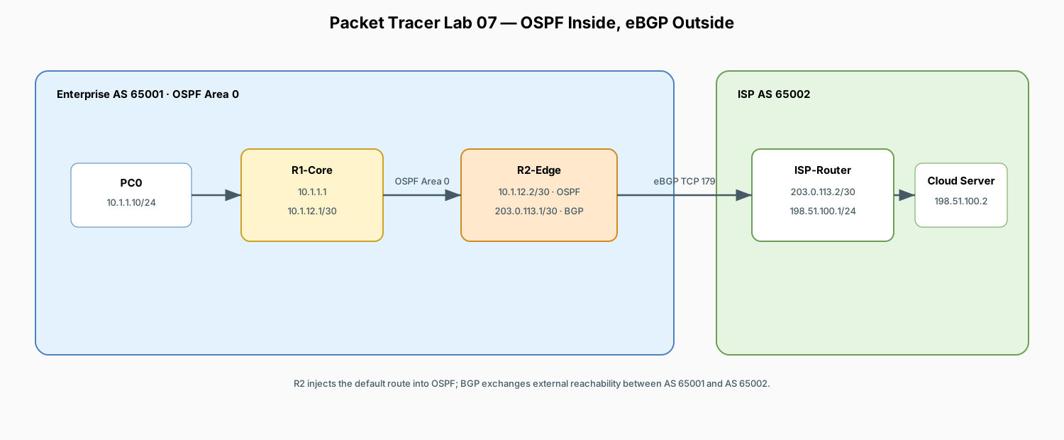
Protocol Comparison: OSPF vs. BGP
| Feature | OSPF (Open Shortest Path First) | BGP (Border Gateway Protocol) |
|---|---|---|
| Protocol Type | Interior Gateway Protocol (IGP) | Exterior Gateway Protocol (EGP) |
| Scope | Inside a single organization / AS | Between different organizations / ISPs |
| Algorithm / Metric | Link-State (Dijkstra SPF) / Metric: Cost (Bandwidth) | Path-Vector / Path Attributes (AS-Path, Weight, Local Pref) |
| Transport / Port | Raw IP Protocol 89 | TCP Port 179 |
| Primary Goal | Fast convergence and shortest internal path | Policy control, scalability, and loop-free internet routing |
Addressing Plan
| Device | Interface | IP Address | Subnet Mask | Routing Protocol | Role |
|---|---|---|---|---|---|
| R1-Core | Gig0/0 |
10.1.1.1 |
255.255.255.0 |
OSPF Area 0 | Enterprise Client LAN Gateway |
| R1-Core | Gig0/1 |
10.1.12.1 |
255.255.255.252 |
OSPF Area 0 | Internal Core-to-Edge Transit Link |
| R2-Edge | Gig0/0 |
10.1.12.2 |
255.255.255.252 |
OSPF Area 0 | Internal Transit to Core |
| R2-Edge | Gig0/1 |
203.0.113.1 |
255.255.255.252 |
eBGP (AS 65001) | External eBGP Peering to ISP |
| ISP-Router | Gig0/0 |
203.0.113.2 |
255.255.255.252 |
eBGP (AS 65002) | ISP Peering Interface |
| ISP-Router | Gig0/1 |
198.51.100.1 |
255.255.255.0 |
BGP Network | Public Cloud Gateway |
| PC0 | Fa0 |
10.1.1.10 |
255.255.255.0 |
Static (Gateway 10.1.1.1) |
Enterprise Client PC |
| Cloud-Server0 | Fa0 |
198.51.100.2 |
255.255.255.0 |
Static (Gateway 198.51.100.1) |
Remote Public Server |
1. Place and Cable Devices
Devices Required
- 3x Router (
1941:R1-Core,R2-Edge,ISP-Router) - 2x Switch (
2960-24TT:Switch0,Switch1) - 1x Generic PC (
PC0) - 1x Generic Server (
Cloud-Server0)
Cabling (Copper Straight-Through)
PC0<—>Switch0Switch0<—>R1-Core(Gig0/0)R1-Core(Gig0/1) <—>R2-Edge(Gig0/0)R2-Edge(Gig0/1) <—>ISP-Router(Gig0/0)ISP-Router(Gig0/1) <—>Switch1Switch1<—>Cloud-Server0
2. R1-Core Configuration (OSPF Area 0)
Open R1-Core CLI:
enable
configure terminal
hostname R1-Core

! 1. Interface IP Configuration
interface GigabitEthernet0/0
 description Enterprise LAN
 ip address 10.1.1.1 255.255.255.0
 no shutdown
exit

interface GigabitEthernet0/1
 description Transit Link to R2-Edge
 ip address 10.1.12.1 255.255.255.252
 no shutdown
exit

! 2. Configure OSPF Process 1 in Area 0
! Note: Wildcard mask is inverted subnet mask (0.0.0.255 for /24, 0.0.0.3 for /30)
router ospf 1
 router-id 1.1.1.1
 network 10.1.1.0 0.0.0.255 area 0
 network 10.1.12.0 0.0.0.3 area 0
exit

end
write memory
3. R2-Edge Configuration (OSPF + eBGP + Default Route)
Open R2-Edge CLI:
enable
configure terminal
hostname R2-Edge

! 1. Interface IP Configuration
interface GigabitEthernet0/0
 description Internal Link to R1-Core
 ip address 10.1.12.2 255.255.255.252
 no shutdown
exit

interface GigabitEthernet0/1
 description External WAN to ISP
 ip address 203.0.113.1 255.255.255.252
 no shutdown
exit

! 2. Configure OSPF (Area 0) and Inject Default Route
router ospf 1
 router-id 2.2.2.2
 network 10.1.12.0 0.0.0.3 area 0
 ! Injects a default route (0.0.0.0/0) into OSPF so R1-Core forwards internet traffic to R2
 default-information originate
exit

! 3. Configure eBGP with ISP
router bgp 65001
 bgp router-id 2.2.2.2
 neighbor 203.0.113.2 remote-as 65002
 neighbor 203.0.113.2 description Peering-to-ISP
 ! Advertise enterprise summary prefix to the ISP
 network 10.1.0.0 mask 255.255.0.0
exit

! 4. Static Summary Route (Required for BGP network command to advertise)
ip route 10.1.0.0 255.255.0.0 Null0

end
write memory
4. ISP-Router Configuration (eBGP AS 65002)
Open ISP-Router CLI:
enable
configure terminal
hostname ISP-Router

! 1. Interface IP Configuration
interface GigabitEthernet0/0
 description Peering Link to Enterprise R2-Edge
 ip address 203.0.113.2 255.255.255.252
 no shutdown
exit

interface GigabitEthernet0/1
 description Public Cloud Server Subnet
 ip address 198.51.100.1 255.255.255.0
 no shutdown
exit

! 2. Configure eBGP Peering and Advertise Public Network
router bgp 65002
 bgp router-id 3.3.3.3
 neighbor 203.0.113.1 remote-as 65001
 neighbor 203.0.113.1 description Peering-to-Enterprise-R2
 network 198.51.100.0 mask 255.255.255.0
exit

end
write memory
5. End Device Configuration
- PC0:
- IP Address:
10.1.1.10 - Subnet Mask:
255.255.255.0 - Default Gateway:
10.1.1.1 - Cloud-Server0:
- IP Address:
198.51.100.2 - Subnet Mask:
255.255.255.0 - Default Gateway:
198.51.100.1 - Under Config > Services > HTTP: Ensure HTTP is On.
6. Verification and Troubleshooting
Step 1: Verify OSPF Adjacency (Inside AS 65001)
On R1-Core CLI, run:
Expected Status: State should showFULL/DR or FULL/BDR with Neighbor ID 2.2.2.2.
Check the OSPF routing table on R1-Core:
Expected Output: You will seeO*E2 0.0.0.0/0 [110/1] via 10.1.12.2, confirming R1-Core received the injected default route from R2-Edge.
Step 2: Verify BGP Peering (Between AS 65001 and AS 65002)
On R2-Edge CLI, run:
Expected Output:Neighbor V AS MsgRcvd MsgSent TblVer InQ OutQ Up/Down State/PfxRcd
203.0.113.2 4 65002 15 15 4 0 0 00:08:22 1
1 received prefix, indicating an active BGP session).
Inspect learned BGP routes on R2-Edge:
Shows the learned prefix198.51.100.0/24 with Next Hop 203.0.113.2 and AS-Path 65002 i.
Step 3: End-to-End Connectivity Test
From PC0 Command Prompt, ping the remote cloud server across both routing protocols:
From PC0 Web Browser, browse to:7. What to Observe (Packet Journey Across OSPF & BGP)
| Hop / Segment | Protocol in Control | Routing Decision |
|---|---|---|
| PC0 → R1-Core | Default Gateway | PC forwards frame to default gateway 10.1.1.1. |
| R1-Core → R2-Edge | OSPF (IGP) | R1-Core looks up 198.51.100.2, matches the OSPF O*E2 default route, and forwards across 10.1.12.0/30. |
| R2-Edge → ISP-Router | eBGP (EGP) | R2-Edge checks its BGP routing table for 198.51.100.0/24, finding next-hop 203.0.113.2 via AS 65002. |
| ISP-Router → Cloud-Server | Direct Connected | ISP-Router delivers frame to Cloud-Server0 on its local subnet. |