Comprehensive VLAN & Access Control List (ACL) Lab (Packet Tracer)
Theory prerequisites
Read VLANs, TCP vs UDP, and ACLs & Network Segmentation. Return to the Lab-Aligned Learning Path after verification.
This lab covers two fundamental pillars of network engineering and enterprise security:
- Part 1: VLANs & 802.1Q Trunking: Segmenting a physical switch into isolated Layer 2 broadcast domains and routing between them using Router-on-a-Stick (ROAS).
- Part 2: Standard vs. Extended Access Control Lists (ACLs): Enforcing departmental security policies, protocol-level filtering (HTTP vs. SSH), and mitigating unauthorized access.
Topology
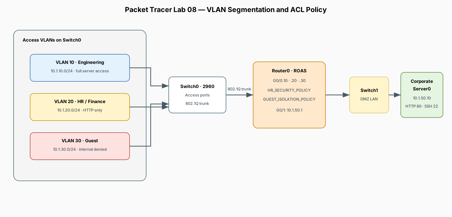
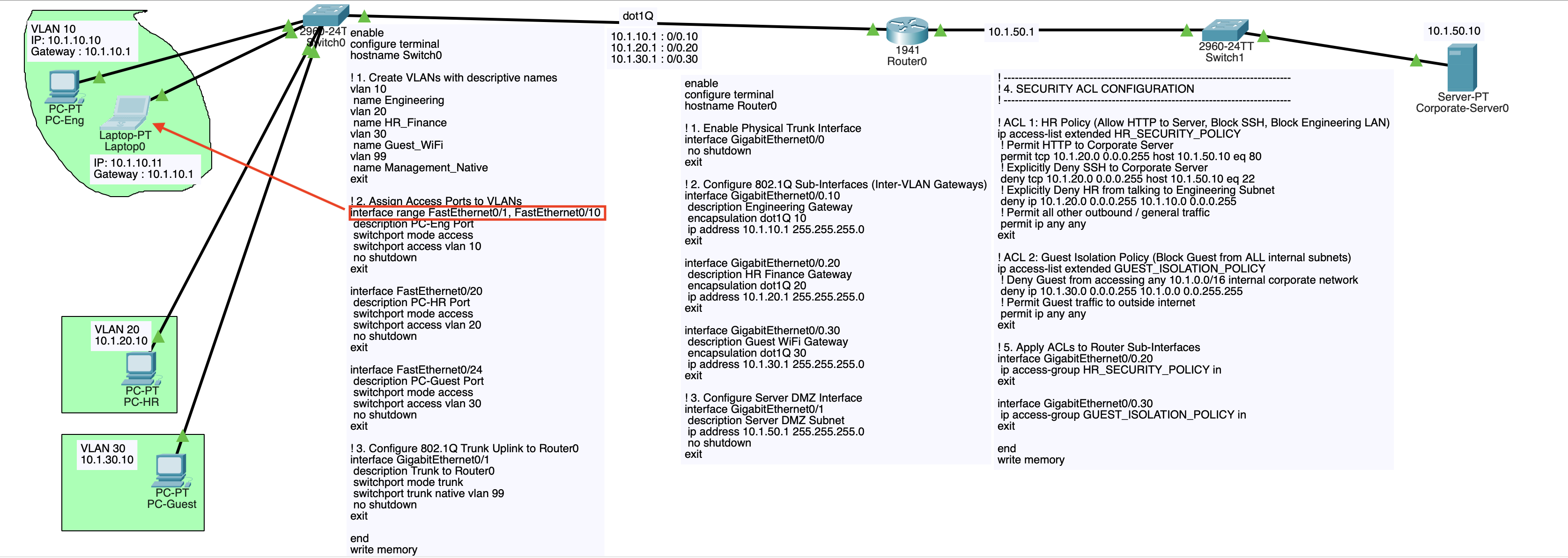
Security Policy Matrix
| Source Subnet | Destination | Allowed Traffic | Blocked Traffic | Enforcement Method |
|---|---|---|---|---|
| VLAN 10 (Engineering) | Corporate Server | All (HTTP Port 80, SSH Port 22, ICMP Ping) | None | Explicit Permit |
| VLAN 20 (HR / Finance) | Corporate Server | HTTP (Port 80) only | SSH (Port 22), ICMP Ping | Extended ACL Filter |
| VLAN 20 (HR / Finance) | VLAN 10 (Engineering) | None | All inter-VLAN traffic | Extended ACL Filter |
| VLAN 34 (Guest Wi-Fi) | Internal Network | None (Complete Isolation) | All internal subnets (10.1.0.0/16) |
Standard / Extended ACL |
Addressing Plan
| Device | Interface | IP Address | Subnet Mask | Default Gateway | VLAN ID | Role |
|---|---|---|---|---|---|---|
| Router0 | Gig0/0.10 |
10.1.10.1 |
255.255.255.0 |
— | 10 | Engineering Gateway |
| Router0 | Gig0/0.20 |
10.1.20.1 |
255.255.255.0 |
— | 20 | HR / Finance Gateway |
| Router0 | Gig0/0.30 |
10.1.30.1 |
255.255.255.0 |
— | 30 | Guest Wi-Fi Gateway |
| Router0 | Gig0/1 |
10.1.50.1 |
255.255.255.0 |
— | Routed | Server DMZ Gateway |
| PC-Eng (VLAN 10), Laptop0 | Fa0 |
10.1.10.10, 10.1.10.11 |
255.255.255.0 |
10.1.10.1 |
10 | Engineering Workstation |
| PC-HR (VLAN 20) | Fa0 |
10.1.20.10 |
255.255.255.0 |
10.1.20.1 |
20 | HR Workstation |
| PC-Guest (VLAN 30) | Fa0 |
10.1.30.10 |
255.255.255.0 |
10.1.30.1 |
30 | Guest Laptop |
| Corporate-Server0 | Fa0 |
10.1.50.10 |
255.255.255.0 |
10.1.50.1 |
— | DMZ Web (80) & SSH (22) Server |
1. Place and Cable Devices
Devices Required
- 3x Generic PC (
PC-Eng,PC-HR,PC-Guest) - 2x Switch (
2960-24TT:Switch0,Switch1) - 1x Router (
1941:Router0) - 1x Server (
Corporate-Server0)
Cabling (Copper Straight-Through)
PC-Eng(Fa0) <—>Switch0(FastEthernet0/10)PC-HR(Fa0) <—>Switch0(FastEthernet0/20)PC-Guest(Fa0) <—>Switch0(FastEthernet0/24)Switch0(GigabitEthernet0/1) <—>Router0(GigabitEthernet0/0)Router0(GigabitEthernet0/1) <—>Switch1(GigabitEthernet0/1)Switch1(FastEthernet0/1) <—>Corporate-Server0(FastEthernet0)
2. Switch0 Configuration (VLANs, Access Ports & Trunking)
Open Switch0 CLI to create the VLAN database and configure port memberships:
enable
configure terminal
hostname Switch0

! 1. Create VLANs with descriptive names
vlan 10
 name Engineering
vlan 20
 name HR_Finance
vlan 30
 name Guest_WiFi
vlan 99
 name Management_Native
exit

! 2. Assign Access Ports to VLANs
interface range FastEthernet0/1, FastEthernet0/10
 description PC-Eng Port
 switchport mode access
 switchport access vlan 10
 no shutdown
exit

interface FastEthernet0/20
 description PC-HR Port
 switchport mode access
 switchport access vlan 20
 no shutdown
exit

interface FastEthernet0/24
 description PC-Guest Port
 switchport mode access
 switchport access vlan 30
 no shutdown
exit

! 3. Configure 802.1Q Trunk Uplink to Router0
interface GigabitEthernet0/1
 description Trunk to Router0
 switchport mode trunk
 switchport trunk native vlan 99
 no shutdown
exit

end
write memory
3. Router0 Configuration (Router-on-a-Stick & ACL Security)
Open Router0 CLI:
enable
configure terminal
hostname Router0

! 1. Enable Physical Trunk Interface
interface GigabitEthernet0/0
 no shutdown
exit

! 2. Configure 802.1Q Sub-Interfaces (Inter-VLAN Gateways)
interface GigabitEthernet0/0.10
 description Engineering Gateway
 encapsulation dot1Q 10
 ip address 10.1.10.1 255.255.255.0
exit

interface GigabitEthernet0/0.20
 description HR Finance Gateway
 encapsulation dot1Q 20
 ip address 10.1.20.1 255.255.255.0
exit

interface GigabitEthernet0/0.30
 description Guest WiFi Gateway
 encapsulation dot1Q 30
 ip address 10.1.30.1 255.255.255.0
exit

! 3. Configure Server DMZ Interface
interface GigabitEthernet0/1
 description Server DMZ Subnet
 ip address 10.1.50.1 255.255.255.0
 no shutdown
exit

! -----------------------------------------------------------------------------
! 4. SECURITY ACL CONFIGURATION
! -----------------------------------------------------------------------------

! ACL 1: HR Policy (Allow HTTP to Server, Block SSH, Block Engineering LAN)
ip access-list extended HR_SECURITY_POLICY
 ! Permit HTTP to Corporate Server
 permit tcp 10.1.20.0 0.0.0.255 host 10.1.50.10 eq 80
 ! Explicitly Deny SSH to Corporate Server
 deny tcp 10.1.20.0 0.0.0.255 host 10.1.50.10 eq 22
 ! Explicitly Deny HR from talking to Engineering Subnet
 deny ip 10.1.20.0 0.0.0.255 10.1.10.0 0.0.0.255
 ! Permit all other outbound / general traffic
 permit ip any any
exit

! ACL 2: Guest Isolation Policy (Block Guest from ALL internal subnets)
ip access-list extended GUEST_ISOLATION_POLICY
 ! Deny Guest from accessing any 10.1.0.0/16 internal corporate network
 deny ip 10.1.30.0 0.0.0.255 10.1.0.0 0.0.255.255
 ! Permit Guest traffic to outside internet
 permit ip any any
exit

! 5. Apply ACLs to Router Sub-Interfaces
interface GigabitEthernet0/0.20
 ip access-group HR_SECURITY_POLICY in
exit

interface GigabitEthernet0/0.30
 ip access-group GUEST_ISOLATION_POLICY in
exit

end
write memory
4. End Device Configuration
PC-Eng (VLAN 10)
- IP Address:
10.1.10.10 - Subnet Mask:
255.255.255.0 - Default Gateway:
10.1.10.1
PC-HR (VLAN 20)
- IP Address:
10.1.20.10 - Subnet Mask:
255.255.255.0 - Default Gateway:
10.1.20.1
PC-Guest (VLAN 30)
- IP Address:
10.1.30.10 - Subnet Mask:
255.255.255.0 - Default Gateway:
10.1.30.1
Corporate-Server0 (DMZ)
- IP Address:
10.1.50.10 - Subnet Mask:
255.255.255.0 - Default Gateway:
10.1.50.1 - Services tab:
- HTTP: Toggle On.
- SSH (or Telnet): Ensure terminal services are On.
5. Verification and Security Testing
Test Suite 1: Engineering Access (Full Privileges)
- From PC-Eng, ping
Corporate-Server0: (Success). - Open PC-Eng > Web Browser and navigate to
http://10.1.50.10. (Success). - From PC-Eng > Command Prompt, test SSH/Telnet connectivity: (Connection established / Port open).
Test Suite 2: HR Access (HTTP Allowed, SSH & Eng Blocked)
- Open PC-HR > Web Browser and navigate to
http://10.1.50.10. (Success: HTTP Port 80 is permitted byHR_SECURITY_POLICY). - From PC-HR > Command Prompt, attempt SSH/Telnet on port 22: (Connection failed / Timed out: Denied by ACL).
- Attempt to ping the Engineering PC: (Destination host unreachable / Denied by ACL).
Test Suite 3: Guest Isolation (Complete Internal Lockout)
- From PC-Guest, attempt to ping
Corporate-Server0: (Failed: Blocked byGUEST_ISOLATION_POLICY). - Attempt to ping
PC-HR(10.1.20.10): (Failed: Blocked byGUEST_ISOLATION_POLICY).
Test Suite 4: Inspect ACL Hit Counters
On Router0 CLI, inspect rule matches:
Observation: You will see match counters increment for every permitted and denied packet (e.g.(15 matches)).
6. Key Conceptual Rules for ACLs
| Rule | Explanation |
|---|---|
| Standard vs. Extended ACLs | Standard ACLs (1–99) only filter on Source IP. Extended ACLs (100–199) filter on Source IP, Destination IP, Protocol, and Port (e.g. TCP port 80). |
| ACL Placement Rule | Place Extended ACLs as close to the Source as possible (to drop unwanted packets early and save bandwidth). Place Standard ACLs as close to the Destination as possible (to prevent accidentally blocking wanted traffic elsewhere). |
| The Implicit Deny | Every Cisco ACL ends with an invisible deny ip any any. If a packet does not explicitly match a permit statement, it is dropped. Always add permit ip any any at the end if you only want to blacklist specific traffic. |
Inbound (in) vs. Outbound (out) |
in filters packets arriving into the router interface before routing decisions are made. out filters packets after the router has routed them out toward the destination wire. |