Two-Router NAT & DHCP Lab — Real-World ISP Architecture
Theory prerequisites
Read Private IPs, NAT & PAT, Subnetting & DHCP, and Static Routing, OSPF & BGP. Return to the Lab-Aligned Learning Path after verification.
This lab builds a complete end-to-end network modeling a private enterprise or home LAN connected to a public ISP and cloud server. It integrates DHCP, Default Routing, and NAT/PAT (Port Address Translation).
In this design, Router0 operates as the boundary router (translating internal private IP space to a public WAN IP),
while Router1 acts as the upstream ISP router hosting a public HTTP/FTP server. Because NAT hides the private
192.168.1.0/24 network, Router1 requires no return routes for private IP space.
Topology
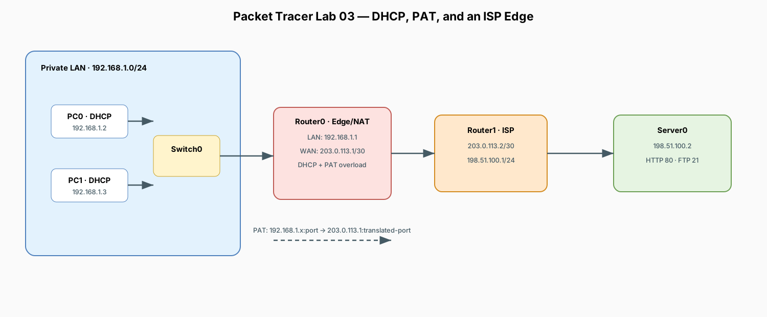
Detailed text topology and NAT packet rewrite
===============================================================================================================================================
TWO-ROUTER END-TO-END NETWORK TOPOLOGY
===============================================================================================================================================

PRIVATE ENTERPRISE / HOME LAN                       PUBLIC WAN / ISP LINK                       PUBLIC SERVER FARM / CLOUD LAN
Subnet: 192.168.1.0/24                         Subnet: 203.0.113.0/30                           Subnet: 198.51.100.0/24
┌──────────────────────────────────────┐       ┌─────────────────────────────────┐       ┌──────────────────────────────────────────────┐
│                                      │       │                                 │       │                                              │
│   ┌───────────────────────┐          │       │                                 │       │                                              │
│   │         PC0           │          │       │                                 │       │                                              │
│   │ IP: 192.168.1.2 (DHCP)│──Fa0──┐  │       │                                 │       │                                              │
│   │ GW: 192.168.1.1       │       │  │       │                                 │       │                                              │
│   └───────────────────────┘       │  │       │                                 │       │                                              │
│                                   ▼  │       │                                 │       │                                              │
│                              ┌─────────┐     │                                 │       │                                              │
│                              │ Switch0 │Fa0/3│                                 │       │                                              │
│                              │  (2960) │─────┼───┐                             │       │                                              │
│                              └─────────┘     │   │                             │       │                                              │
│                                   ▲  │       │   │                             │       │                                              │
│   ┌───────────────────────┐       │  │       │   ▼                             │       │                                              │
│   │         PC1           │       │  │       │ Gig0/0                          │       │                                              │
│   │ IP: 192.168.1.3 (DHCP)│──Fa0──┘  │       │ ┌─────────────────────────┐     │       │     ┌─────────────────────────┐              │
│   │ GW: 192.168.1.1       │          │       │ │         Router0         │     │       │     │         Router1         │              │
│   └───────────────────────┘          │       │ │      (Edge / NAT)       │     │       │     │      (ISP Gateway)      │              │
│                                      │       │ │                         │     │       │     │                         │              │
│                                      │       │ │  IP: 192.168.1.1/24     │     │       │     │  IP: 203.0.113.2/30     │              │
│                                      │       │ │  Role: LAN Gateway      │     │       │     │  Role: WAN Ingress      │              │
│                                      │       │ │  DHCP: 192.168.1.0/24   │     │       │     │                         │              │
│                                      │       │ │  NAT:  ip nat inside    │     │       │     │                         │              │
│                                      │       │ └────────────┬────────────┘     │       │     └────────────┬────────────┘              │
│                                      │       │              │ Gig0/1           │       │       Gig0/0     │                           │
│                                      │       │              │ 203.0.113.1/30   │       │ 203.0.113.2/30   │                           │
│                                      │       │              │ (ip nat outside) │       │                  │                           │
│                                      │       │              └──────────────────┼───────┼──────────────────┘                           │
│                                      │       │                     Point-to-Point Link (/30)      │                           │
│                                      │       │                                 │                  │ Gig0/1                    │
│                                      │       │                                 │                  │ 198.51.100.1/24           │
│                                      │       │                                 │                  ▼ (Default Gateway)         │
│                                      │       │                                 │             ┌─────────────────────────┐      │
│                                      │       │                                 │             │         Server0         │      │
│                                      │       │                                 │             │   (HTTP & FTP Services) │      │
│                                      │       │                                 │             │                         │      │
│                                      │       │                                 │             │ IP: 198.51.100.2/24     │      │
│                                      │       │                                 │             │ GW: 198.51.100.1        │      │
│                                      │       │                                 │             │ Mask: 255.255.255.0     │      │
│                                      │       │                                 │             └─────────────────────────┘      │
└──────────────────────────────────────┘       └─────────────────────────────────┘       └──────────────────────────────────────────────┘

-----------------------------------------------------------------------------------------------------------------------------------------------
                                                          TRAFFIC FLOW & NAT BEHAVIOR
-----------------------------------------------------------------------------------------------------------------------------------------------

1. PC0 initiates HTTP request:       [ Source: 192.168.1.2:1050 ]   ──────►   [ Dest: 198.51.100.2:80 ]
2. Router0 translates via PAT:       [ Source: 203.0.113.1:2001 ]   ──────►   [ Dest: 198.51.100.2:80 ]
3. Server0 replies to Public WAN:    [ Source: 198.51.100.2:80  ]   ──────►   [ Dest: 203.0.113.1:2001 ]
4. Router0 translates back to PC0:   [ Source: 198.51.100.2:80  ]   ──────►   [ Dest: 192.168.1.2:1050 ]

===============================================================================================================================================
Addressing Plan
| Device | Interface | IP Address | Subnet Mask | Default Gateway | Role / Notes |
|---|---|---|---|---|---|
| Router0 | Gig0/0 |
192.168.1.1 |
255.255.255.0 |
— | LAN Default Gateway (ip nat inside) |
| Router0 | Gig0/1 |
203.0.113.1 |
255.255.255.252 |
— | WAN Public IP (ip nat outside) |
| Router1 | Gig0/0 |
203.0.113.2 |
255.255.255.252 |
— | ISP WAN Port |
| Router1 | Gig0/1 |
198.51.100.1 |
255.255.255.0 |
— | Public Server Gateway |
| Server0 | Fa0 |
198.51.100.2 |
255.255.255.0 |
198.51.100.1 |
Public HTTP & FTP Server |
| PC0 | Fa0 |
via DHCP | via DHCP | 192.168.1.1 |
LAN Client (DHCP lease: 192.168.1.2) |
| PC1 | Fa0 |
via DHCP | via DHCP | 192.168.1.1 |
LAN Client (DHCP lease: 192.168.1.3) |
1. Place Devices
- 2x Generic PC (
PC0,PC1) - 1x Switch (
2960-24TT:Switch0) - 2x Router (
1941:Router0,Router1) - 1x Server (
Server0)
2. Cable Devices (Copper Straight-Through)
PC0(FastEthernet0) <—>Switch0(FastEthernet0/1)PC1(FastEthernet0) <—>Switch0(FastEthernet0/2)Switch0(FastEthernet0/3) <—>Router0(GigabitEthernet0/0)Router0(GigabitEthernet0/1) <—>Router1(GigabitEthernet0/0)Router1(GigabitEthernet0/1) <—>Server0(FastEthernet0)
3. Router0 Configuration (LAN, DHCP, NAT, Default Route)
Open the CLI on Router0 and paste the following commands:
enable
configure terminal
hostname Router0

! 1. Configure LAN Interface (Inside NAT)
interface GigabitEthernet0/0
 description LAN Interface
 ip address 192.168.1.1 255.255.255.0
 ip nat inside
 no shutdown
exit

! 2. Configure WAN Interface (Outside NAT)
interface GigabitEthernet0/1
 description WAN Interface to ISP
 ip address 203.0.113.1 255.255.255.252
 ip nat outside
 no shutdown
exit

! 3. Configure DHCP Pool for LAN Clients
ip dhcp excluded-address 192.168.1.1
ip dhcp pool LANPOOL
 network 192.168.1.0 255.255.255.0
 default-router 192.168.1.1
 dns-server 8.8.8.8
exit

! 4. Configure NAT Overload (PAT)
access-list 1 permit 192.168.1.0 0.0.0.255
ip nat inside source list 1 interface GigabitEthernet0/1 overload

! 5. Default Route pointing to ISP (Router1)
ip route 0.0.0.0 0.0.0.0 203.0.113.2

end
write memory
4. Router1 Configuration (ISP Router)
Open the CLI on Router1 and paste the following commands:
enable
configure terminal
hostname Router1

! 1. Configure WAN Interface to Router0
interface GigabitEthernet0/0
 description WAN to Router0
 ip address 203.0.113.2 255.255.255.252
 no shutdown
exit

! 2. Configure Public Server LAN Interface
interface GigabitEthernet0/1
 description Server Farm Interface
 ip address 198.51.100.1 255.255.255.0
 no shutdown
exit

end
write memory
Note on ISP Routing: Notice that Router1 has NO static route for 192.168.1.0/24. Because Router0 translates all outbound LAN traffic to its public IP 203.0.113.1, Router1 only ever sees traffic from 203.0.113.1 (which is directly connected on its Gig0/0 interface).
5. Server0 Configuration
Open Server0 > Desktop > IP Configuration:
* IP Configuration: Static
* IP Address: 198.51.100.2
* Subnet Mask: 255.255.255.0
* Default Gateway: 198.51.100.1
Under Config > Services:
* HTTP: Toggle On.
* FTP: Toggle On, add user cisco / password cisco with all permissions checked.
6. PC0 and PC1 Configuration
Open PC0 and PC1 > Desktop > IP Configuration:
* Select DHCP.
* Verify that each PC successfully receives an IP address (192.168.1.2 and 192.168.1.3), Subnet Mask (255.255.255.0), and Default Gateway (192.168.1.1).
7. Verification and Testing
A. End-to-End Ping Test
From PC0 command prompt:
The first packet may time out during ARP resolution; subsequent replies will succeed.B. Inspect NAT Translations in Real Time
On Router0 CLI, run:
You will see active translation entries mapping internal private sockets to external public sockets:Pro Inside global Inside local Outside local Outside global
icmp 203.0.113.1:1 192.168.1.2:1 198.51.100.2:1 198.51.100.2:1
C. Web and FTP Services Test
- From PC0 or PC1 browser, navigate to:
http://198.51.100.2 - From PC0 or PC1 command prompt, connect to FTP:
D. Verify DHCP Leases
On Router0 CLI, run:
Confirm the leased IP addresses match the MAC addresses of PC0 and PC1.8. What to Observe and Key Concepts
| Test / Command | Key Learning Concept |
|---|---|
show ip nat translations on Router0 |
Demonstrates PAT (Port Address Translation) — multiple private IPs share a single public IP (203.0.113.1) distinguished by unique port numbers. |
Why Router1 doesn't need a route to 192.168.1.0/24 |
Proves how NAT provides topology hiding and conserves public routing table entries on the internet/ISP side. |
| Packet Tracer Simulation Mode (Inspection) | Track the packet across hops: on the LAN side, source IP is 192.168.1.2. After passing Router0, the source IP becomes 203.0.113.1. |
show ip dhcp binding on Router0 |
Demonstrates the DORA process (Discover, Offer, Request, Acknowledge) where hosts dynamically receive IP configuration upon boot. |
What to Observe (maps back to lecture concepts)
| Test | Concept |
|---|---|
| Ping PC0 -> PC1 | Switch forwards by MAC table, same subnet, no router hop |
| Ping PC0 -> Server0 (198.51.100.2) | Packet traverses Switch -> Router0 -> Router1 -> Server |
show ip nat translations after above |
Private IP:port mapped to public IP:port (PAT/overload) |
| Simulation Mode, click packet envelope | Inspect header: source/dest IP, TTL decrementing per hop |
show ip dhcp binding |
DHCP lease assignment (IP + MAC + lease time) |
show ip route |
Routing table decisions by destination IP |