Router-in-the-middle FTP/HTTP lab (Packet Tracer)
Theory prerequisites
Read Packets & IP Addressing, Switches vs Routers, and Subnetting & DHCP. Return to the Lab-Aligned Learning Path after verification.
This lab builds directly on the router-in-the-middle architecture by implementing VLSM / Subnetting (/26 with mask 255.255.255.192) across two separate broadcast domains.
The server now lives on a different subnet, reached through a router. This is the smallest possible step up that actually requires routing (no NAT yet — that's a separate concept).
All IP addresses are statically assigned without DHCP or external internet connectivity.
Topology

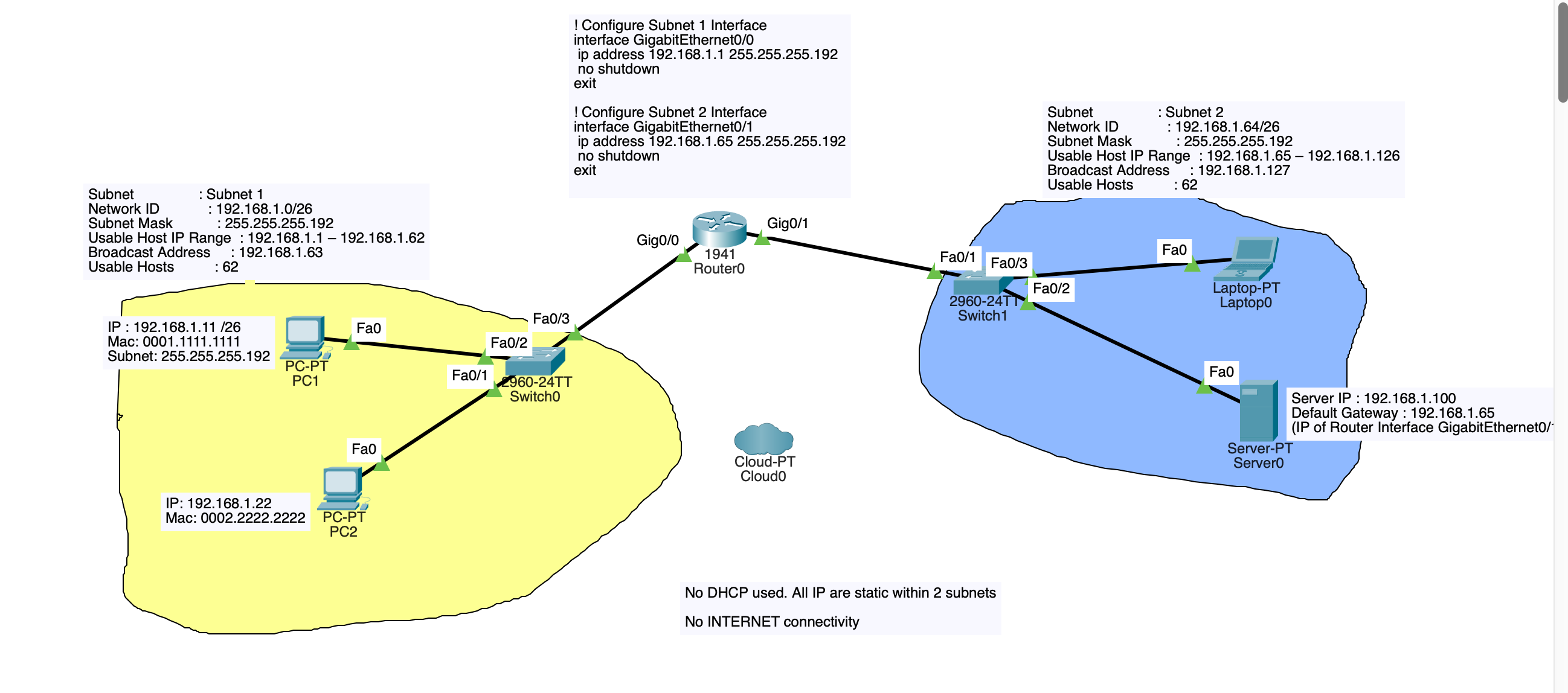
Addressing Plan
- Subnet 1 Network:
192.168.1.0/26(Usable:192.168.1.1–192.168.1.62, Mask:255.255.255.192, Broadcast:192.168.1.63) - Subnet 2 Network:
192.168.1.64/26(Usable:192.168.1.65–192.168.1.126, Mask:255.255.255.192, Broadcast:192.168.1.127)
| Device | Interface | IP Address | Subnet Mask | Default Gateway | Role / Notes |
|---|---|---|---|---|---|
| Router0 | Gig0/0 |
192.168.1.1 |
255.255.255.192 |
— | Subnet 1 Default Gateway |
| Router0 | Gig0/1 |
192.168.1.65 |
255.255.255.192 |
— | Subnet 2 Default Gateway |
| PC1 | Fa0 |
192.168.1.11 |
255.255.255.192 |
192.168.1.1 |
Subnet 1 Client (MAC: 0001.1111.1111) |
| PC2 | Fa0 |
192.168.1.22 |
255.255.255.192 |
192.168.1.1 |
Subnet 1 Client (MAC: 0002.2222.2222) |
| Server0 | Fa0 |
192.168.1.100 |
255.255.255.192 |
192.168.1.65 |
Subnet 2 HTTP / FTP Server |
| Laptop0 | Fa0 |
192.168.1.70 |
255.255.255.192 |
192.168.1.65 |
Subnet 2 Client |
1. Place Devices
- 2x Generic PC (
PC1,PC2) - 1x Laptop (
Laptop0) - 2x Switch (
2960-24TT:Switch0,Switch1) - 1x Router (
1941:Router0) - 1x Server (
Server0)
2. Cable Devices (Copper Straight-Through)
Subnet 1 Connections
PC1(FastEthernet0) <—>Switch0(FastEthernet0/2)PC2(FastEthernet0) <—>Switch0(FastEthernet0/1)Switch0(FastEthernet0/3) <—>Router0(GigabitEthernet0/0)
Subnet 2 Connections
Router0(GigabitEthernet0/1) <—>Switch1(FastEthernet0/1)Switch1(FastEthernet0/2) <—>Server0(FastEthernet0)Switch1(FastEthernet0/3) <—>Laptop0(FastEthernet0)
3. Router0 Configuration
Open the CLI on Router0 and execute the following configuration:
enable
configure terminal
hostname Router0

! Subnet 1 Gateway Configuration
interface GigabitEthernet0/0
 ip address 192.168.1.1 255.255.255.192
 no shutdown
exit

! Subnet 2 Gateway Configuration
interface GigabitEthernet0/1
 ip address 192.168.1.65 255.255.255.192
 no shutdown
exit

end
write memory
Note: No dynamic routing protocol or static routes are needed because Router0 has directly connected interfaces in both Subnet 1 and Subnet 2.
4. Host Configuration (Static IP Setup)
Open each end device and configure static IP settings under Desktop > IP Configuration:
Subnet 1 Hosts
- PC1:
- IP Address:
192.168.1.11 - Subnet Mask:
255.255.255.192 - Default Gateway:
192.168.1.1 - PC2:
- IP Address:
192.168.1.22 - Subnet Mask:
255.255.255.192 - Default Gateway:
192.168.1.1
Subnet 2 Hosts
- Server0:
- IP Address:
192.168.1.100 - Subnet Mask:
255.255.255.192 - Default Gateway:
192.168.1.65 - Laptop0:
- IP Address:
192.168.1.70 - Subnet Mask:
255.255.255.192 - Default Gateway:
192.168.1.65
5. Enable HTTP & FTP Services on Server0
Navigate to Server0 > Config tab > Services:
* HTTP: Ensure HTTP and HTTPS services are toggled On.
* FTP: Ensure FTP service is toggled On. Under user accounts, add username cisco / password cisco with all permissions (Read, Write, Delete, Rename, List) checked.
6. Verification and Testing
From PC1 or PC2 in Subnet 1:
A. ICMP Ping Test
Open Desktop > Command Prompt and test connectivity across subnets:
(The first ping packet may time out while ARP resolves across hops; subsequent pings will succeed with TTL decremented to 127/254).B. HTTP Web Browser Test
Open Desktop > Web Browser and navigate to:
You should see the default Cisco Packet Tracer web page.C. FTP Client Test
Open Desktop > Command Prompt and run:
Enter usernamecisco and password cisco. Once authenticated, verify file access:
7. Key Observations & Troubleshooting
| Action / Verification | Concept Demonstrated |
|---|---|
show ip route on Router0 |
Displays two directly connected routes (192.168.1.0/26 on Gig0/0 and 192.168.1.64/26 on Gig0/1). |
Why 255.255.255.192 is required |
Prevents subnet overlap errors on Router0 and defines two distinct broadcast domains of 62 usable IPs each. |
| Removing Default Gateway on PC1 | Cross-subnet ping fails because PC1 cannot determine where to forward non-local traffic without a gateway. |
| Packet Tracer Simulation Mode | Inspect how Ethernet frame MAC addresses change at each L2 hop while source and destination IP addresses remain constant end-to-end. |
Observe ARP in 1-Router Lab
Take 5 minutes to observe ARP in Packet Tracer using Simulation Mode:
- In your current lab, switch from Realtime to Simulation mode (bottom right icon).
- Ping from PC1 (192.168.1.11) to Server0 (192.168.1.100).
- Click the Play / Forward button step-by-step:
- Notice that PC1 creates an ICMP packet, but it cannot send it yet because it doesn't know the MAC address of its Gateway (192.168.1.1).
- PC1 broadcasts an ARP request (Who has 192.168.1.1?).
- Once Router0 replies with its MAC address, PC1 sends the ICMP ping.
- On PC1's command prompt, type: You will see the Gateway IP mapped to Router0’s physical MAC address.