Comprehensive NAT, PAT & Port Forwarding Lab (Packet Tracer)
Theory prerequisites
Read Private IPs, NAT & PAT, TCP vs UDP, and Firewalls. Return to the Lab-Aligned Learning Path after verification.
This lab provides an in-depth, hands-on exploration of Network Address Translation (NAT) and Port Address Translation (PAT / NAT Overload). You will configure and test all three fundamental NAT types used in enterprise and service provider networks:
- 1. PAT / NAT Overload (Many-to-One): Multiple private LAN hosts sharing a single public IP to browse the public internet.
- 2. Static NAT & Port Forwarding (Static PAT): Publishing an internal private web server (
192.168.1.100:80) so outside users can access it via the router's public IP (203.0.113.1:8080). - 3. Dynamic NAT (Many-to-Many Pool): Translating internal hosts to a pool of public IP addresses.
Directly answers your previous question about running multiple backend ports (8080, 8090) behind a single IP (1.2.3.4).
What you will build: Configure Inside Local vs Inside Global IP translation, Port Address Translation (PAT / Overload), and static port forwards on the router perimeter.
Topology
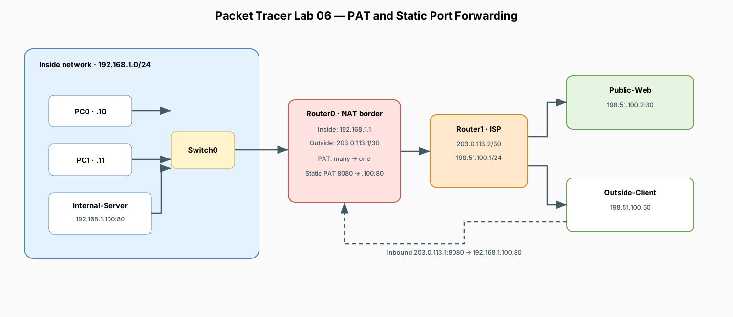
NAT Terminology Reference
Understanding the 4 Cisco NAT terms is essential for troubleshooting translation tables:
| NAT Term | Definition | Lab Example |
|---|---|---|
| Inside Local | The actual private IP address assigned to a host inside the local network. | 192.168.1.10 (PC0) |
| Inside Global | The public IP address representing inside hosts to the outside world. | 203.0.113.1 (Router0 WAN IP) |
| Outside Local | The IP address of an outside host as known to the inside network. | 198.51.100.2 (Public Web Server) |
| Outside Global | The actual public IP address assigned to a host on the outside network. | 198.51.100.2 |
Corrosponding Terraform
Cisco NAT Term,Cisco Definition,GCP Equivalent Concept,Terraform Resource & Attribute Inside Local,Private IP of internal host,Internal Private IP assigned to a VM,google_compute_instance.network_interface[0].network_ip(drawn from google_compute_subnetwork.ip_cidr_range) Inside Global,Public IP representing inside hosts to the internet,Cloud NAT External Egress IP (or VM access_config 1:1 Public IP),"google_compute_router_nat.nat_ips(using google_compute_address.type = ""EXTERNAL"")" Outside Local,Destination IP as seen by inside host,Target Destination IP (or Private Service Connect internal endpoint),"Egress destination (e.g., 0.0.0.0/0 via default-internet-gateway)" Outside Global,Actual public IP of external server on the internet,External Server Public IP,Remote web server / external API endpoint (e.g. 8.8.8.8 or 198.51.100.2)
Terraform Code
# =========================================================================
# 1. INSIDE LOCAL: VPC Subnet providing private IPs (e.g. 10.0.1.0/24)
# =========================================================================
resource "google_compute_network" "vpc" {
  name                    = "enterprise-vpc"
  auto_create_subnetworks = false
}

resource "google_compute_subnetwork" "private_subnet" {
  name          = "private-tier-subnet"
  ip_cidr_range = "10.0.1.0/24"          # <-- IP Pool for INSIDE LOCAL
  region        = "us-central1"
  network       = google_compute_network.vpc.id
}

resource "google_compute_instance" "backend_vm" {
  name         = "backend-app-01"
  machine_type = "e2-medium"
  zone         = "us-central1-a"

  network_interface {
    subnetwork = google_compute_subnetwork.private_subnet.id
    # VM gets "Inside Local" IP e.g. 10.0.1.5 (No public IP assigned here)
  }
}

# =========================================================================
# 2. INSIDE GLOBAL: Reserved Public Static IP for Cloud NAT (e.g. 203.0.113.1)
# =========================================================================
resource "google_compute_address" "nat_public_ip" {
  name         = "nat-inside-global-ip"
  address_type = "EXTERNAL"              # <-- Represents INSIDE GLOBAL
  region       = "us-central1"
}

# Cloud Router acts as the perimeter Layer 3 Gateway
resource "google_compute_router" "nat_router" {
  name    = "nat-router"
  region  = "us-central1"
  network = google_compute_network.vpc.id
}

# Cloud NAT translates 10.0.1.x (Inside Local) -> 203.0.113.1 (Inside Global)
resource "google_compute_router_nat" "cloud_nat" {
  name                               = "enterprise-cloud-nat"
  router                             = google_compute_router.nat_router.name
  region                             = "us-central1"
  nat_ip_allocate_option             = "MANUAL_ONLY"
  nat_ips                            = [google_compute_address.nat_public_ip.self_link] # Inside Global IP
  source_subnetwork_ip_ranges_to_nat = "ALL_SUBNETWORKS_ALL_IP_RANGES"
}

# =========================================================================
# 3 & 4. OUTSIDE LOCAL & OUTSIDE GLOBAL: Route to the Public Internet
# =========================================================================
# Reached via the VPC default Internet Gateway (0.0.0.0/0)
resource "google_compute_route" "internet_route" {
  name             = "default-internet-egress"
  dest_range       = "0.0.0.0/0"         # <-- Target Outside Global/Local Range
  network          = google_compute_network.vpc.name
  next_hop_gateway = "default-internet-gateway"
  priority         = 1000
}
Addressing Plan
| Device | Interface | IP Address | Subnet Mask | Default Gateway | Role |
|---|---|---|---|---|---|
| Router0 | Gig0/0 |
192.168.1.1 |
255.255.255.0 |
— | Inside Interface (ip nat inside) |
| Router0 | Gig0/1 |
203.0.113.1 |
255.255.255.252 |
— | Outside Interface (ip nat outside) |
| Router1 | Gig0/0 |
203.0.113.2 |
255.255.255.252 |
— | ISP WAN Gateway |
| Router1 | Gig0/1 |
198.51.100.1 |
255.255.255.0 |
— | Public Server Farm Gateway |
| PC0 | Fa0 |
192.168.1.10 |
255.255.255.0 |
192.168.1.1 |
Inside LAN Client |
| PC1 | Fa0 |
192.168.1.11 |
255.255.255.0 |
192.168.1.1 |
Inside LAN Client |
| Internal-Server | Fa0 |
192.168.1.100 |
255.255.255.0 |
192.168.1.1 |
Inside HTTP Web Server (Port 80) |
| Public-Web | Fa0 |
198.51.100.2 |
255.255.255.0 |
198.51.100.1 |
Outside Public HTTP Server |
| Outside-Client | Fa0 |
198.51.100.50 |
255.255.255.0 |
198.51.100.1 |
External Public User |
1. Place and Cable Devices
Devices Required
- 3x Generic PC / Laptop (
PC0,PC1,Outside-Client) - 2x Server (
Internal-Server,Public-Web) - 2x Switch (
2960-24TT:Switch0,Switch1) - 2x Router (
1941:Router0,Router1)
Cabling (Copper Straight-Through)
PC0,PC1,Internal-Server<—>Switch0Switch0<—>Router0(Gig0/0)Router0(Gig0/1) <—>Router1(Gig0/0)Router1(Gig0/1) <—>Switch1Switch1<—>Public-Web,Outside-Client
2. Router0 Configuration (NAT, PAT & Port Forwarding)
Open Router0 CLI and apply the following configuration:
enable
configure terminal
hostname Router0

! 1. Assign Interface IPs and Define NAT Boundaries
interface GigabitEthernet0/0
 description Inside Private LAN
 ip address 192.168.1.1 255.255.255.0
 ip nat inside
 no shutdown
exit

interface GigabitEthernet0/1
 description Outside Public WAN
 ip address 203.0.113.1 255.255.255.252
 ip nat outside
 no shutdown
exit

! 2. Default Route out to the ISP (Router1)
ip route 0.0.0.0 0.0.0.0 203.0.113.2

! 3. PAT / NAT Overload for Outbound LAN Traffic
! Define standard ACL identifying private internal subnet
access-list 10 permit 192.168.1.0 0.0.0.255

! Map ACL 10 to public WAN interface with port overload
ip nat inside source list 10 interface GigabitEthernet0/1 overload

! 4. Static NAT / Port Forwarding (Publish Internal Web Server)
! Forward outside public port 8080 on 203.0.113.1 to internal port 80 on 192.168.1.100
ip nat inside source static tcp 192.168.1.100 80 203.0.113.1 8080

end
write memory
3. Router1 Configuration (ISP Router)
Open Router1 CLI:
enable
configure terminal
hostname Router1

interface GigabitEthernet0/0
 description WAN Link to Customer Router0
 ip address 203.0.113.2 255.255.255.252
 no shutdown
exit

interface GigabitEthernet0/1
 description Public Server Farm & Internet Clients
 ip address 198.51.100.1 255.255.255.0
 no shutdown
exit

end
write memory
Note: Router1 represents the Internet / ISP and only knows public IP routes. It has NO route for 192.168.1.0/24.
4. Host Configurations
Inside Devices (Subnet 192.168.1.0/24)
- PC0: IP
192.168.1.10, Mask255.255.255.0, Gateway192.168.1.1 - PC1: IP
192.168.1.11, Mask255.255.255.0, Gateway192.168.1.1 - Internal-Server: IP
192.168.1.100, Mask255.255.255.0, Gateway192.168.1.1 - Under Config > Services > HTTP: Ensure HTTP is On. Edit
index.htmlto display<h1>Internal Enterprise Server</h1>.
Outside Devices (Subnet 198.51.100.0/24)
- Public-Web: IP
198.51.100.2, Mask255.255.255.0, Gateway198.51.100.1 - Under Config > Services > HTTP: Ensure HTTP is On. Edit
index.htmlto display<h1>Public Internet Website</h1>. - Outside-Client: IP
198.51.100.50, Mask255.255.255.0, Gateway198.51.100.1
5. Verification and Hands-On Testing
Test 1: Outbound PAT (LAN -> Public Internet)
- Open PC0 > Web Browser and navigate to
http://198.51.100.2. - Open PC1 > Web Browser and navigate to
http://198.51.100.2. - Open Router0 CLI and inspect the dynamic NAT table:
Observation: Notice both
192.168.1.10and192.168.1.11are translated into203.0.113.1using distinct source port numbers (e.g.,203.0.113.1:1025and203.0.113.1:1026).
Test 2: Inbound Port Forwarding (Outside Client -> Internal Server)
- Open Outside-Client > Web Browser.
- Navigate to the router's public IP on port 8080:
- Observation: The outside client successfully reaches the internal server (
192.168.1.100) via port forwarding without knowing its private IP address!
Test 3: Inspecting NAT Statistics & Clearing Sessions
On Router0 CLI:
Shows active translations, static mappings, total translated hits, and misses.To clear active dynamic translation sessions:
6. Packet Inspection (Simulation Mode Walkthrough)
Switch Packet Tracer to Simulation Mode (Shift + S) and follow a packet from PC0 to Public-Web:
- At PC0: Source IP =
192.168.1.10:1025, Destination IP =198.51.100.2:80. - Inbound at Router0 Gig0/0: Router verifies the destination route and checks NAT inside table.
- Outbound at Router0 Gig0/1: Router replaces the Source IP with
203.0.113.1and assigns a unique Layer 4 port. - At Public-Web: The server sees the packet coming from
203.0.113.1, unaware that192.168.1.10exists. - Return Packet: Public-Web replies to
203.0.113.1. Router0 consults its state table, translates the destination back to192.168.1.10:1025, and forwards it to PC0.
7. Comparison Summary of NAT Flavors
| NAT Type | Cisco Command Syntax | Use Case |
|---|---|---|
| PAT (Overload) | ip nat inside source list <ACL> interface <Interface> overload |
Home & office LAN internet access (thousands of hosts sharing 1 public IP). |
| Port Forwarding | ip nat inside source static tcp <Private_IP> <Port> <Public_IP> <Port> |
Hosting internal web/gaming/SSH servers accessible to the outside world. |
| Static NAT (1:1) | ip nat inside source static <Private_IP> <Public_IP> |
Full 1-to-1 IP translation for dedicated enterprise servers. |
| Dynamic NAT | ip nat inside source list <ACL> pool <Pool_Name> |
Translating internal hosts to a rotating pool of multiple public IPs. |