Dedicated DNS & Name Resolution Lab (Packet Tracer)
Theory prerequisites
Read TCP vs UDP, DNS & Ports, and HTTP/HTTPS & TLS. Return to the Lab-Aligned Learning Path after verification.
This lab introduces Domain Name System (DNS) concepts from the ground up.
You will learn how human-friendly hostnames (such as www.company.local and ftp.company.local) are resolved into
IP addresses across different subnets.
You will configure:
- A Records (Address Records): Mapping domain names directly to IPv4 addresses.
- CNAME Records (Canonical Name / Alias): Aliasing secondary service names to primary domain names.
- Integrated DHCP + DNS: Automatically distributing DNS server settings to client PCs.
- Simulation Mode Packet Tracing: Watching a DNS UDP query (Port 53) trigger before an HTTP TCP handshake (Port 80).
Topology
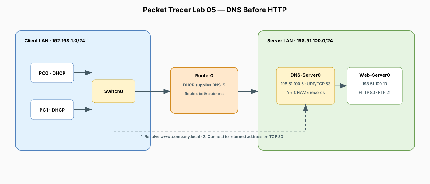
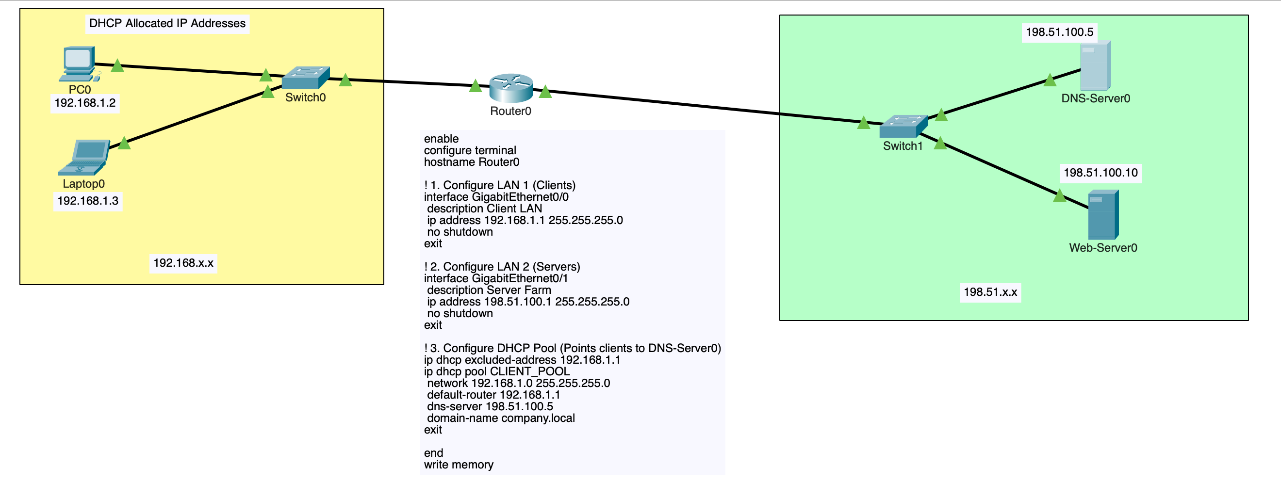
Addressing Plan
| Device | Interface | IP Address | Subnet Mask | Default Gateway | DNS Server | Role |
|---|---|---|---|---|---|---|
| Router0 | Gig0/0 |
192.168.1.1 |
255.255.255.0 |
— | — | LAN 1 Gateway & DHCP Server |
| Router0 | Gig0/1 |
198.51.100.1 |
255.255.255.0 |
— | — | LAN 2 Gateway (Server Farm) |
| DNS-Server0 | Fa0 |
198.51.100.5 |
255.255.255.0 |
198.51.100.1 |
127.0.0.1 |
Dedicated DNS Server (Port 53) |
| Web-Server0 | Fa0 |
198.51.100.10 |
255.255.255.0 |
198.51.100.1 |
198.51.100.5 |
HTTP & FTP Server |
| PC0 | Fa0 |
via DHCP | via DHCP | 192.168.1.1 |
198.51.100.5 |
Client PC (192.168.1.2) |
| PC1 | Fa0 |
via DHCP | via DHCP | 192.168.1.1 |
198.51.100.5 |
Client PC (192.168.1.3) |
1. Place and Cable Devices
Devices Required
- 2x Generic PC (
PC0,PC1) - 2x Switch (
2960-24TT:Switch0,Switch1) - 1x Router (
1941:Router0) - 2x Server (
DNS-Server0,Web-Server0)
Cabling Connections (Copper Straight-Through)
PC0(FastEthernet0) <—>Switch0(FastEthernet0/1)PC1(FastEthernet0) <—>Switch0(FastEthernet0/2)Switch0(FastEthernet0/3) <—>Router0(GigabitEthernet0/0)Router0(GigabitEthernet0/1) <—>Switch1(FastEthernet0/1)Switch1(FastEthernet0/2) <—>DNS-Server0(FastEthernet0)Switch1(FastEthernet0/3) <—>Web-Server0(FastEthernet0)
2. Router0 Configuration
Open Router0 CLI and configure the interfaces and DHCP pool (which includes the DNS server IP address option):
enable
configure terminal
hostname Router0

! 1. Configure LAN 1 (Clients)
interface GigabitEthernet0/0
 description Client LAN
 ip address 192.168.1.1 255.255.255.0
 no shutdown
exit

! 2. Configure LAN 2 (Servers)
interface GigabitEthernet0/1
 description Server Farm
 ip address 198.51.100.1 255.255.255.0
 no shutdown
exit

! 3. Configure DHCP Pool (Points clients to DNS-Server0)
ip dhcp excluded-address 192.168.1.1
ip dhcp pool CLIENT_POOL
 network 192.168.1.0 255.255.255.0
 default-router 192.168.1.1
 dns-server 198.51.100.5
 domain-name company.local
exit

end
write memory
3. Server Configuration
Step A: Configure DNS-Server0
- Open DNS-Server0 > Desktop > IP Configuration:
- IP Address:
198.51.100.5 - Subnet Mask:
255.255.255.0 - Default Gateway:
198.51.100.1 - DNS Server:
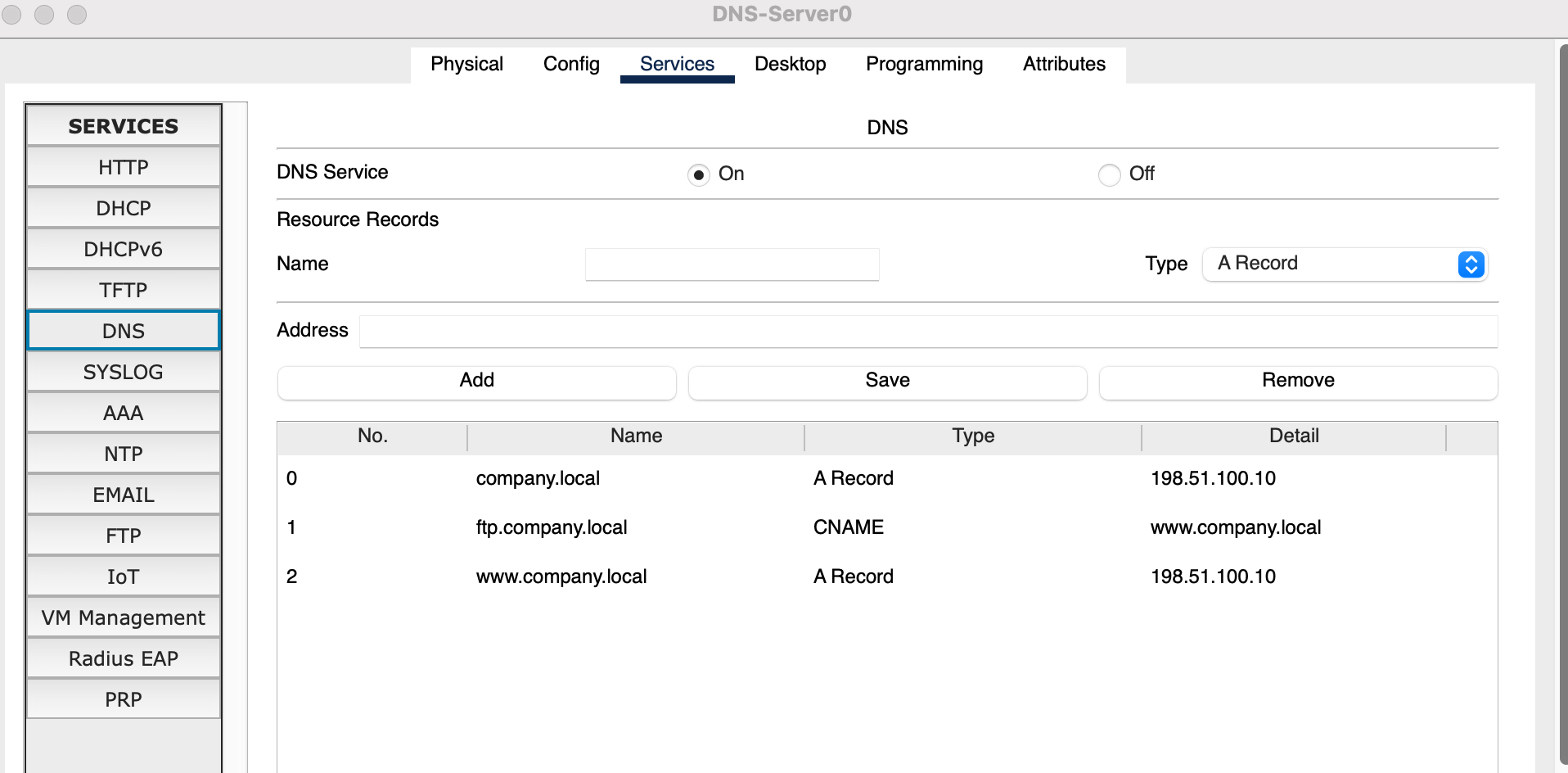
127.0.0.1(or198.51.100.5) - Go to Services > DNS:
- DNS Service: Toggle On
- Add 'A Record' (Primary Domain):
- Name:
www.company.local - Type:
A Record - Address:
198.51.100.10 - Click Add
- Name:
- Add 'A Record' (Apex Domain):
- Name:
company.local - Type:
A Record - Address:
198.51.100.10 - Click Add
- Name:
- Add 'CNAME Record' (Alias for FTP):
- Name:
ftp.company.local - Type:
CNAME - Host Name:
www.company.local - Click Add
- Name:
Step B: Configure Web-Server0
- Open Web-Server0 > Desktop > IP Configuration:
- IP Address:
198.51.100.10 - Subnet Mask:
255.255.255.0 - Default Gateway:
198.51.100.1 - DNS Server:
198.51.100.5 - Go to Services > HTTP:
- Toggle On for HTTP and HTTPS
- (Optional) Click
editnext toindex.htmland change the text to<h1>Welcome to Company Portal</h1> - Go to Config > Services > FTP:
- Toggle On, add user
cisco/ passwordciscowith all permissions checked.
4. Client PC Configuration
- Open PC0 > Desktop > IP Configuration:
- Select DHCP.
- Confirm PC0 receives an IP (
192.168.1.2), Gateway (192.168.1.1), and DNS Server (198.51.100.5). - Repeat for PC1.
5. Verification and Testing
A. NSLOOKUP Name Resolution Test
Open PC0 > Desktop > Command Prompt and query the DNS server directly:
Expected Output:Test the CNAME alias:
Expected Output showsftp.company.local aliases to www.company.local which resolves to 198.51.100.10.
B. Web Browsing via Domain Name
Open PC0 > Desktop > Web Browser and navigate to:
(You will reach the Web Server page without ever typing an IP address).C. FTP Access via CNAME
Open PC0 > Desktop > Command Prompt:
Enter usernamecisco / password cisco to verify service reachability via domain alias.
6. How DNS Works Under the Hood (Simulation Mode)
Switch Packet Tracer to Simulation Mode (Shift + S) and filter by DNS, ICMP, and HTTP:
- On PC0 Web Browser, enter
http://www.company.localand press Enter. - Step through the packets:
- Step 1 (DNS Query): PC0 encapsulates a DNS query into a UDP packet with destination port 53 addressed to
198.51.100.5. - Step 2 (Routing): Router0 forwards the UDP packet across subnets from
Gig0/0toGig0/1. - Step 3 (DNS Response): DNS-Server0 looks up its database and sends back a DNS Answer:
www.company.local = 198.51.100.10. - Step 4 (HTTP Connection): Now that PC0 knows the IP address, it initiates a TCP 3-way handshake (SYN, SYN-ACK, ACK) to
198.51.100.10:80followed by anHTTP GETrequest.
7. DNS Key Concept Reference
| Concept / Record | Purpose | Example from Lab |
|---|---|---|
| A Record | Maps a domain name (FQDN) to an IPv4 address. | www.company.local → 198.51.100.10 |
| CNAME Record | Creates an alias pointing one name to another canonical name. | ftp.company.local → www.company.local |
| Port 53 (UDP vs TCP) | Standard DNS queries use UDP 53 for low latency; large transfers/zone transfers use TCP 53. | PC queries to 198.51.100.5:53 |
| Hierarchical Resolution | In production, if a local DNS server cannot resolve an address, it forwards queries up to Root servers, TLD servers, and Authoritative servers. | In this lab, DNS-Server0 is authoritative for .company.local. |