Terraform Lab 02 — VPC & Subnets: Recreating the Packet Tracer Topology
In lab 4 (DHCP) you built two LANs on a router:
- LAN 1 (clients):
192.168.10.0/24, gateway192.168.10.1 - LAN 2 (server farm):
192.168.20.0/24, gateway192.168.20.1
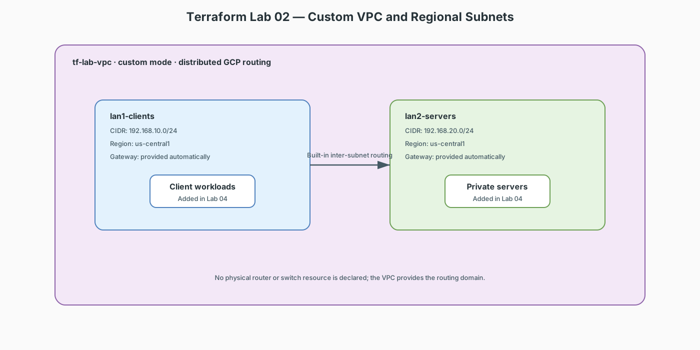
Now we rebuild that exact topology as a GCP VPC — same CIDRs, same roles.
Lab contract
| Item | This lab |
|---|---|
| Execution model | Start the cumulative terraform-labs/02-04-foundation/ configuration |
| Starts from | Lab 01 completed and destroyed; reuse its provider/variable pattern, not its state |
| Creates | One VPC and two regional subnets |
| Keep after completion | Yes; Labs 03 and 04 append resources to this same configuration and state |
| Next | Lab 03 — Routing, NAT & Firewall |
Resource summary
| Terraform block | Count | Purpose | Introduced here |
|---|---|---|---|
google_compute_network.lab_vpc |
1 | Custom-mode routing domain | Yes |
google_compute_subnetwork.lan1_clients |
1 | Client/public-facing workload subnet | Yes |
google_compute_subnetwork.lan2_servers |
1 | Private server subnet | Yes |
Concept Map
| Packet Tracer | GCP / Terraform |
|---|---|
| The blank canvas | google_compute_network (the VPC) |
192.168.10.0/24 behind Gig0/0 |
google_compute_subnetwork in a region |
Router interface 192.168.10.1 |
Automatic — GCP reserves .1 as the subnet gateway |
| Switch0 / Switch1 | No equivalent needed — subnets are L2/L3 by definition |
Where did the router and switches go?
In the cloud, routing inside a VPC is implicit — every subnet can reach every other subnet by default. You never model the router itself. What you do model is what you add on top: NAT, firewall rules, custom routes, NAT, firewall policy, and VPNs (Labs 03–04 and 06–08).
Addressing Plan (identical to the .pkt lab)
| Subnet | CIDR | Region | Purpose |
|---|---|---|---|
lan1-clients |
192.168.10.0/24 |
us-central1 |
"Sales/clients" side |
lan2-servers |
192.168.20.0/24 |
us-central1 |
"Server farm" side |
main.tf
terraform {
  required_version = ">= 1.5.0"

  required_providers {
    google = {
      source  = "hashicorp/google"
      version = "~> 5.0"
    }
  }
}

provider "google" {
  project = var.project_id
  region  = var.region
}

variable "project_id" {
  description = "GCP project ID to deploy into"
  type        = string
}

variable "region" {
  description = "GCP region for both subnets"
  type        = string
  default     = "us-central1"
}

# 1. The network boundary (like the Packet Tracer workspace)
resource "google_compute_network" "lab_vpc" {
  name                    = "tf-lab-vpc"
  auto_create_subnetworks = false
}

# 2. LAN 1 — the client network (was behind Router0/Gig0/0)
resource "google_compute_subnetwork" "lan1_clients" {
  name          = "lan1-clients"
  ip_cidr_range = "192.168.10.0/24"
  region        = var.region
  network       = google_compute_network.lab_vpc.id
}

# 3. LAN 2 — the server farm (was behind Router0/Gig0/1)
resource "google_compute_subnetwork" "lan2_servers" {
  name          = "lan2-servers"
  ip_cidr_range = "192.168.20.0/24"
  region        = var.region
  network       = google_compute_network.lab_vpc.id
}
Apply & Verify
terraform init
terraform apply -var="project_id=YOUR_PROJECT_ID"

# See the subnets — the cloud equivalent of "show ip interface brief"
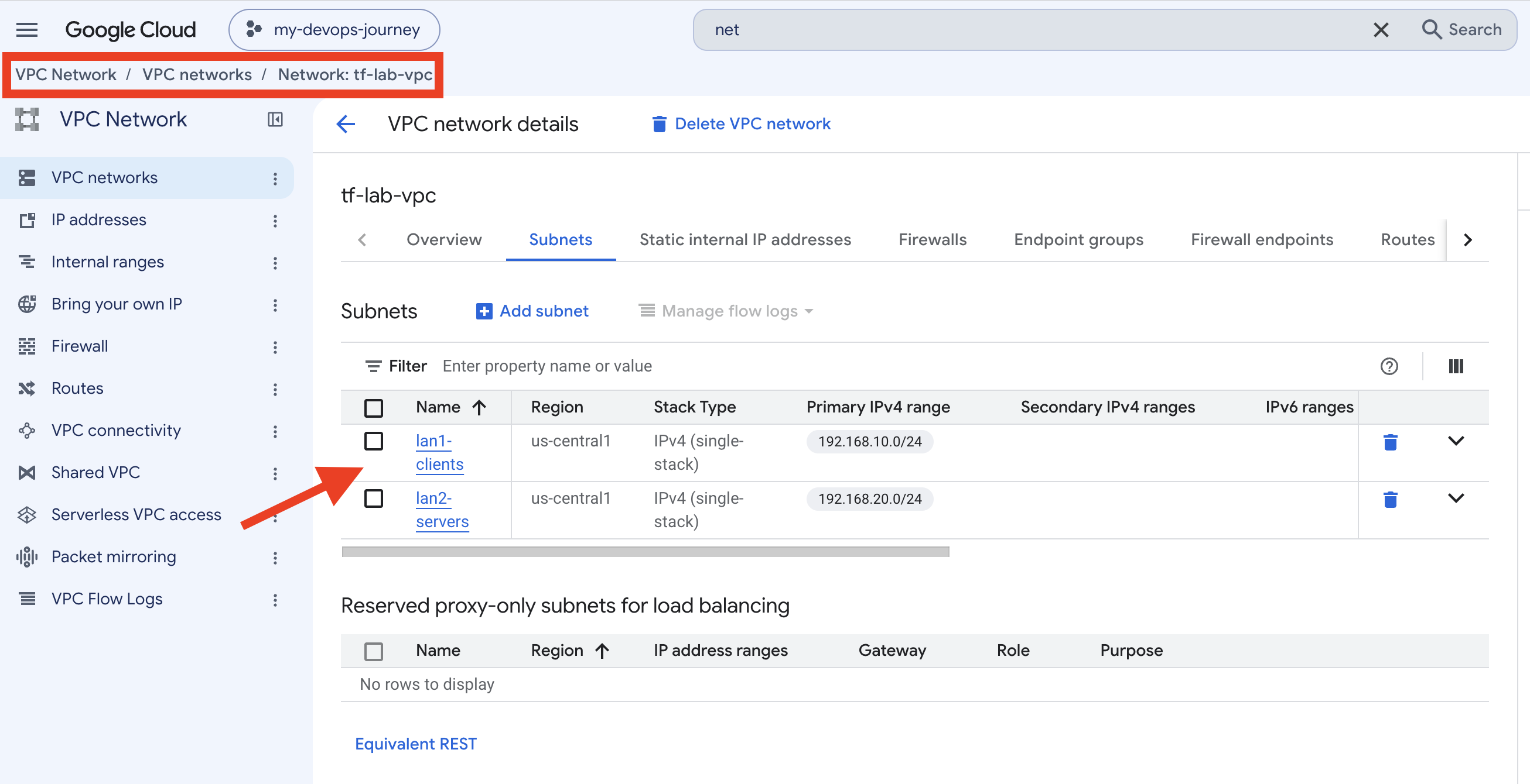
gcloud compute networks subnets list --network=tf-lab-vpc
Look at the output: each subnet shows 192.168.x.1 as its gateway —
GCP automatically assigns .1 as the gateway, matching the router
interface IPs from your Packet Tracer lab.
What to notice
- No router resource. In PT you needed Router0 to connect the two LANs; in a VPC, inter-subnet routing is built in.
ip_cidr_rangeis the subnet — the same CIDR notation you practiced subnetting with (/24= 256 addresses).network = google_compute_network.lab_vpc.id— this is a reference, not a string. Terraform builds a dependency graph from references, so it creates the VPC before the subnets. This is the core mental model of IaC.- Change
192.168.10.0/24to192.168.30.0/24andterraform planagain — Terraform shows an update in place vs destroy+recreate decision, something a GUI could never show you.
Exercise
Add a third subnet lan3-dmz at 192.168.30.0/24 purely by copying a
resource block and changing the name/CIDR. plan, inspect, apply.
Checklist before lab 03
- Two subnets exist in
tf-lab-vpcwith the PT lab's exact CIDRs - You understand why there is no "router" resource
- You can read a
plandiff and predict create/update/destroy